Completed on: 2024-06-20
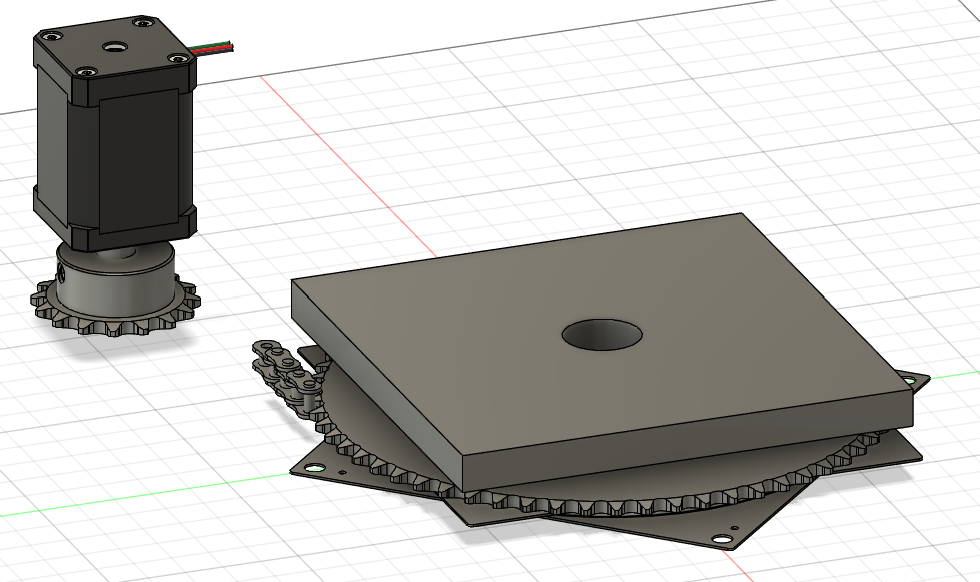
Here we see the rough designs for the ST-FMR assembly. The final result can be seen below but I never bothered to model it completely together and I never made a model for the housing of the motor opting to manually design that. The key design elements are a whole in the entire rotating assembly so we can place a pole in the middle to hold our sample and then use the sprocket to connect the assembly to the motor so it can turn. Honestly, it was pretty fun to get to use a chain and sprocket in a design and I'm very pleased with how it turned out. I think the major drawbacks of the design is the slightly weaker than anticipated magnetic field due to the modular pole design (see below).
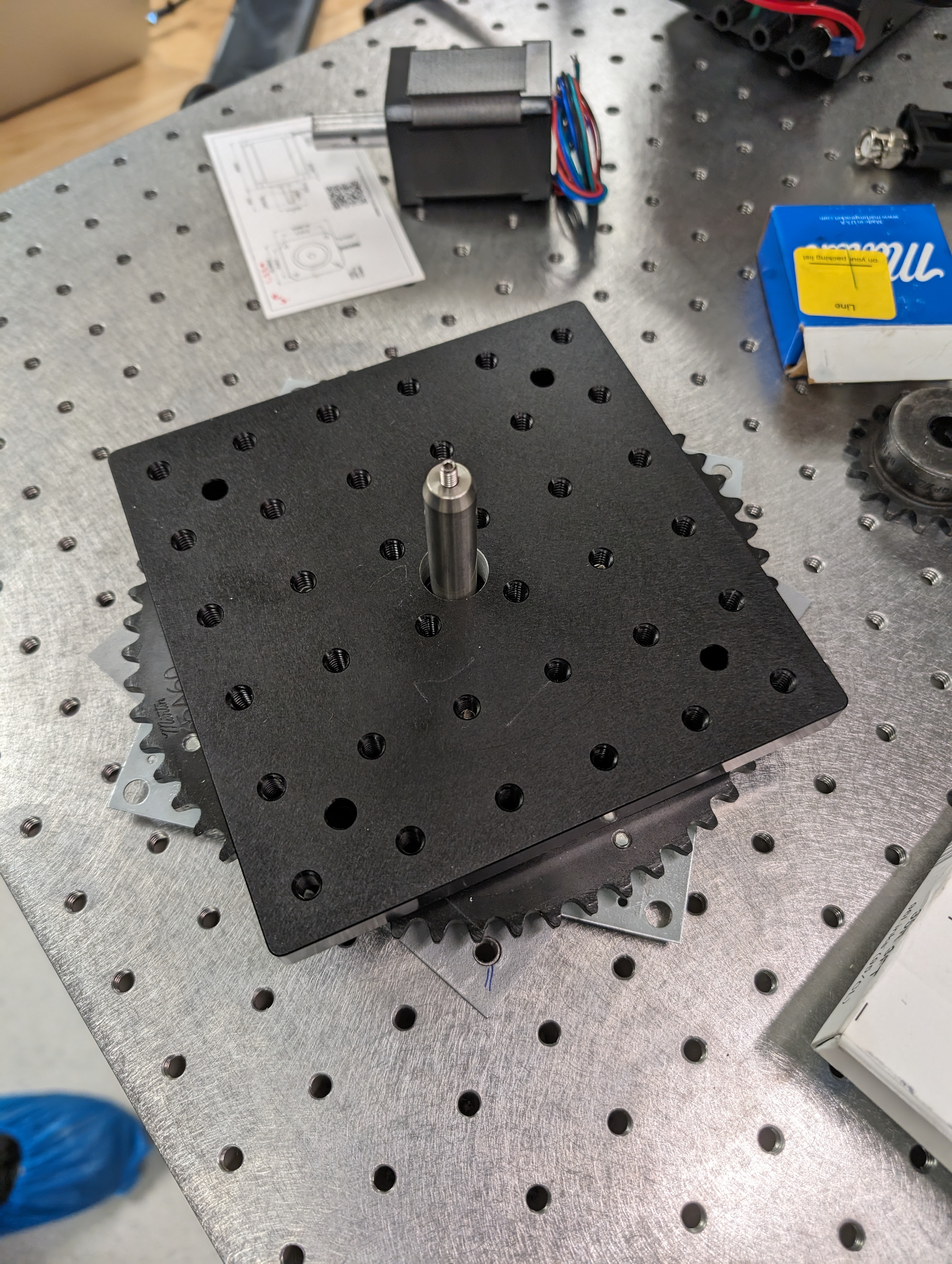
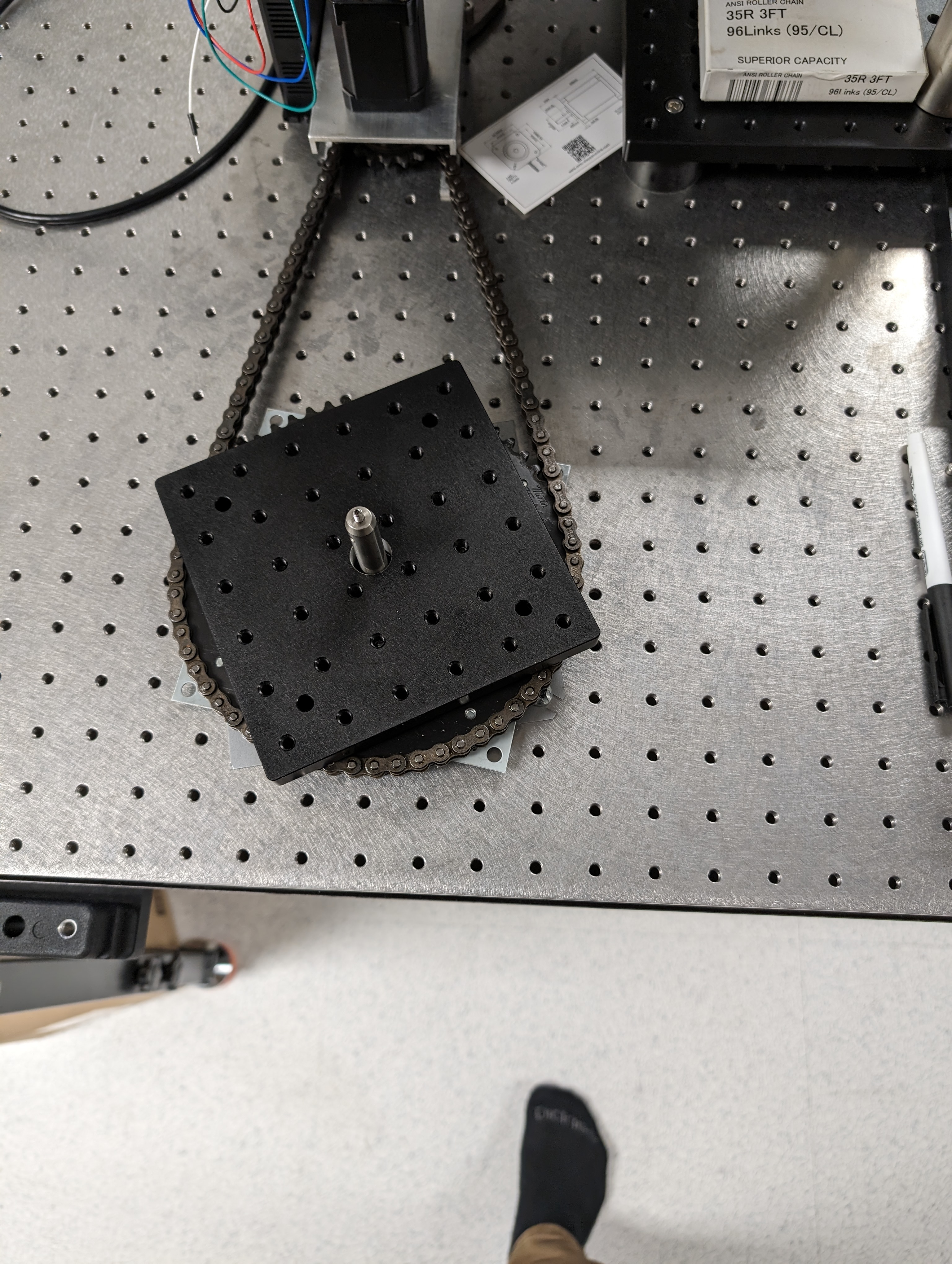
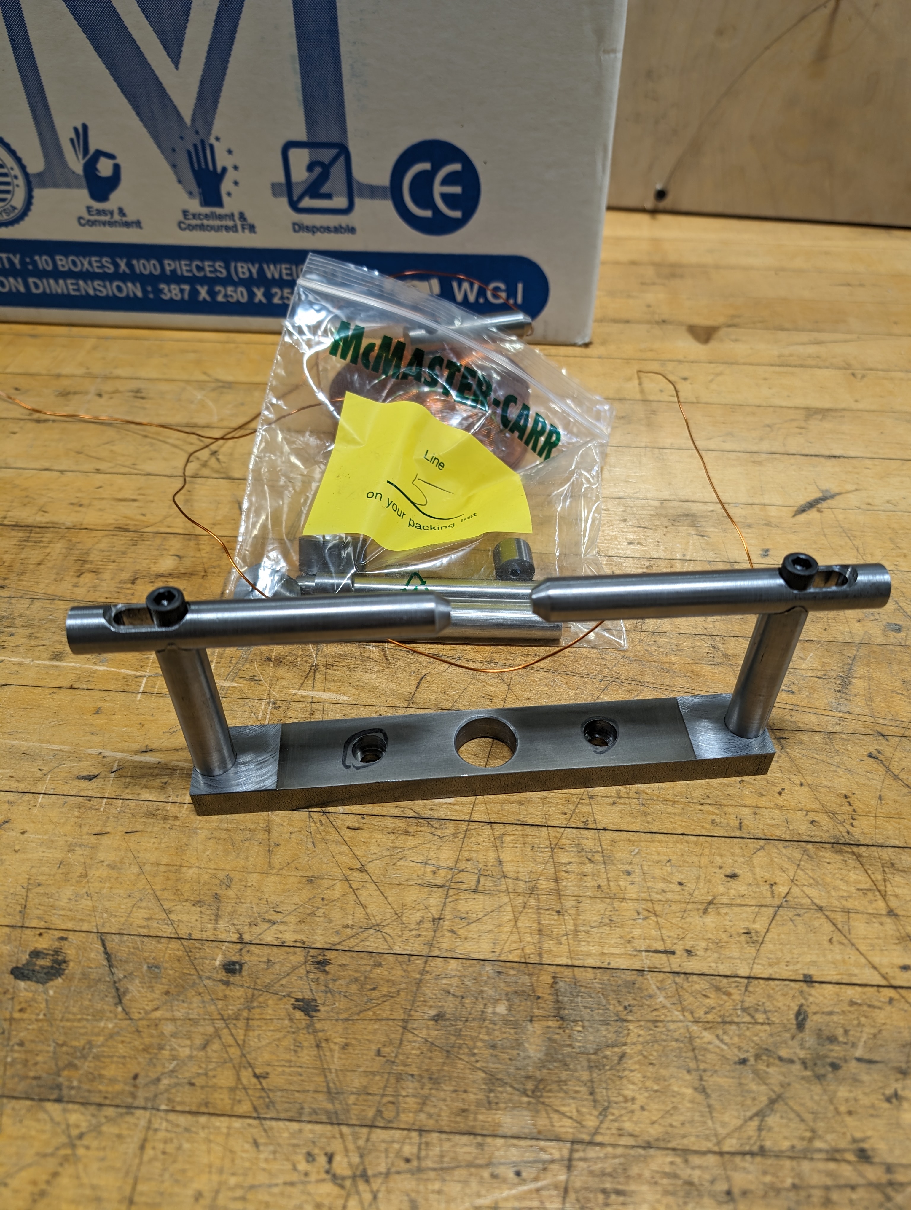
Now we can see the fruit of our labors, and of course a special shoutout to the machine shop for some beautiful machining (I did not have the time to machine it myself). It took a few small edits to allow us to mount it to the optical table but after all was said and done we have quite a robust system. The first image shows me testing the assembly before we place the magnet atop the rotating platform. The middle image shows the motor connected to the assembly via a chain and I start to calibrate the gear (sprocket) ratios for the code to precisely turn the magnet platform. The third image depicts the bare magnet core (technically v2 but details) that will be mounted onto the assembly. It is important to note here that the modular pole spacing design drastically reduces the flux going through the core leading to suboptimal field strengths -- so there is clear room for improvement (but since the assembly is modular you can just get different pole pieces). Also as a fun aside, I included the middle photo since I think my footwear is rather amusing -- just don't tell EHS.


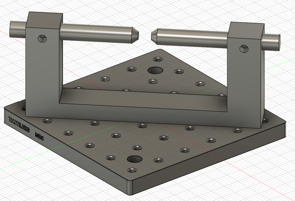
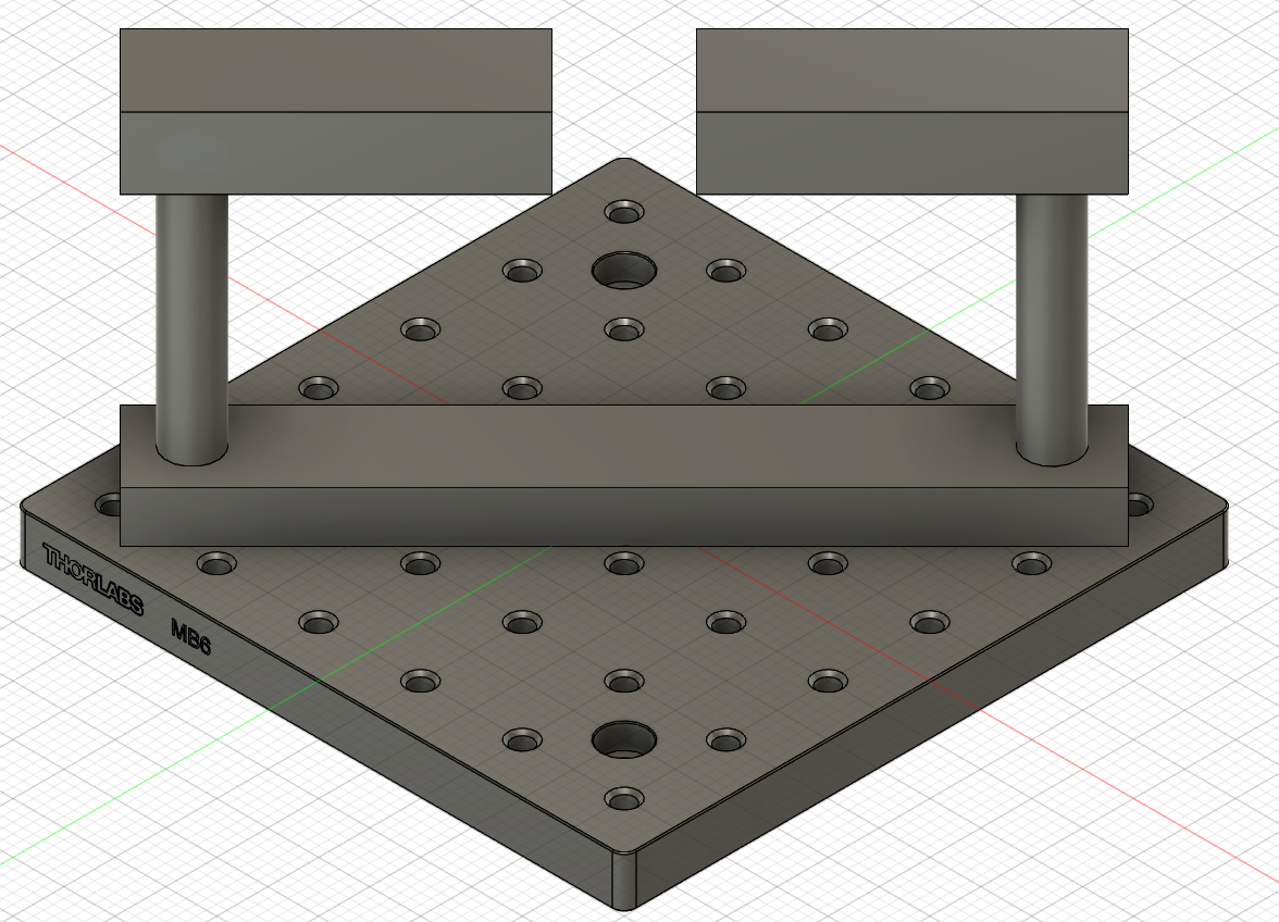
Here we see the final assembly of the ST-FMR setup. These images are up to date as of summer of 2025 and represent the cleaned up view of the ST-FMR setup. The first image gives us a close up of the
A short video of me machining the sample holder (pole) to the desired thickness. Of note, the poles themselves are actually modular allowing one to screw in new caps to change the relative thickness of the sample stage to allow the magnet poles to be brought in closer or farther apart.
The STFMR setup in action! Courtesy of my labmate Liang Here we can see that it operates completely autonomously using the software suite I developed and Liang applied. You can see the gaussmeter probe mounted securely allowing for accurate field feedback control as well as a thermocouple connected to the magnet to mitigate runaway.
This project probably took the longest to complete. Above you have seen some cool photos detailing my experience trying to create a Spin-Torque Ferromagnetic Resonance (ST-FMR) setup for our lab. If you've had the chance to take a look through the timeline at the vector magnet (fun fact the vector magnets original design was completed before the magnet maker was even operational) you will see that I noted it was initially intended to be used for the ST-FMR setup. Unfortunately not everything works out the way we want it too (and HAD it worked, it would have made our lives MUCH easier). So to draw up the needs of our ST-FMR setup -- I was asked to design it with a relatively strong field (>1000 Oe) that can be precisely rotated to give any arbitrary in-plane field orientation. Most importantly, we must be able to land a Ground-Signal-Ground (GSG) probe on our sample that is mechanically isolated from the magnet assembly. Remember this part, as it dictated the design considerations of the setup. We already had a probe manipulator with 6 axes rotation that I was to incorporate in the design as well as some probes. Sadly, some quick math showed that it was not going to be possible to use the probe tips we already had as the probe manipulator would not be able to clear the magnet's poles (Hint: Why was my original vector magnet design flat at the top? -- see I knew there was a reason for that silly design). Thus I was forced to make a compromise and found some very neat probes that gave us some vertical clearance so the probe manipulator could clear the magnet assembly. Working in the constraints of the probes vertical clearance we were limited in where we could place the magnetic coils, as if we wanted to put them on the horizontal poles of the magnet they would interfere with the clearance of the probe, allowing for a very low turn/length count -> too small of a field. With that consideration, like the vector magnet I opted to mount the coils vertically and hope the flux closure of the low-carbon steel would be enough. As this was a more complicated project I opted to roughly sketch out the assembly before consulting the experts in the machine shop for the final touches. I opted for a design that allows variable pole spacing (to fit sample of different sizes and a way to get more field for small samples). Thus the beautiful monstrosity you see above was born. It consists of a lazy susan mounted to a thorlabs plate that we can screw in the magnet with a hole running through the entire assembly to allow us to connect the sample holder to the optical table the entire system rests on. Thus the magnet is entirely mechanically isolated from the sample and probe itself only connected via the optical table which is unavoidable and acts as a large sink regardless so unimportant. This allows the electrical noise in the magnet to not interfere mechanically with our measurements. Thus we have created a magnet that can rotate to any arbitrary angle completely isolated from our measurement apparatus. Now, we could have stopped there but who wants to manually rotate anything? So I opted to put a large gear (sprocket for you technical folks) in between the lazy susan and the thorlabs plate to allow us to use a combination of a sprocket and chain. Thus we can precisely control the magnitude and direction of the magnetic field in the sample entirely from the computer allowing for automated measurements (since these can take ours to run we can run them overnight when less people are in the lab and less noise sources are around). All that's left is to code the system up and hope it works! (Spoiler it did). The final touches (as seen in the final images) were done by my labmate Liang (who I was tasked to help make the setup for) where he finalized some of the code based on my previous experience at Berkeley. Thus a robust instrument was born hopefully to outlast my PhD career. A few fun side tangents, later on we had Alex in our lab create a nice enclosure for the stepper motor driver to better secure everything in place.